Author Topic: Red Caboose GP9 remotor  (Read 5505 times)

Bob

  • Global Moderator
  • Full Member
  • *****
  • Posts: 162
    • Bob's web site
Red Caboose GP9 remotor
« on: February 28, 2024, 08:21:49 AM »
The Pittman 8414 and its shorter brother 8313 are two of the most common motors used in O-scale diesels. However, they are physically large and known to be current hogs. The 8414 armature resistance is very low, resulting in a stall current of 7.9A. That gives them a lot of starting torque but that torque can't be sustained without overheating.

When driving an 8414 the back-EMF measurement algorithm of ESU decoders tends to induce a lot of electrical noise at the rails due to large current spikes. This noise can send other decoders run in consist out-to-lunch, particularly when running more than ~20 feet away from a DCC booster. The distance factor is due to bus wire inductance, not resistance. ESU recommended that we install coreless motors if possible. When out-to-lunch the decoder stops responding to DCC commands. This failure has also happened with a pair of dual vertical motor Atlas F3s.

I recently procured some Swiss-made Portescap coreless motors from an auction site. These have a stall current of only 1.2A and that should permit operation with an HO decoder. They are much smaller than a Pittman yet they produce 1.7 times the torque per Amp and they are rated for a slightly higher continuous torque.

Therefore the first reason for a new motor is the hope of eliminating out-to-lunch decoders when run in consist.

Recently one of the forum members, Big Trains James, contacted me and shared his work fitting a large Tang Band 1931 speaker module inside the car body of a Red Caboose GP9. Now that caught my interest! He described milling the sides of the plastic enclosure to make it just narrow enough to fit in the RC shell.

I had already started learning Fusion 360 to make a new fuel tank that could hold a smaller TB 1925S speaker module, so my attention turned to see if there could be enough room above a smaller Portescap motor to fit a 1931 firing up and out of the dynamic brake fan.

In CAD I designed a Portescap mount that lowers the motor shaft by about 1/4 inch relative to the original Pittman. Now it appears that, as Gene Wilder exclaimed in the movie Young Frankenstein, "It might just work!"

This is a work-in-progress CAD drawing of the new mount.


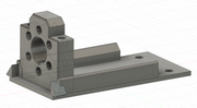
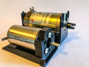
Here's a side-by-side comparison of the Portescap and Pittman motors. The new mount is 3D printed in ABS. Lock washers will be installed under the 4-40 screw heads.


This is certainly not the final design. I plan to add features to prevent wires from tangling in the drive train, and add a mounting platform for a small PC board to manage wires to the trucks and decoder.

The second reason for a new motor is to get hear more booming bass.

Bob

Big Train James

  • Newbie
  • *
  • Posts: 19
Re: Red Caboose GP9 remotor
« Reply #1 on: February 28, 2024, 09:00:20 AM »
That was quick!

I'm happy to post the speaker mod description to the forum.  I can do it here or start a separate thread, which ever you think is best.

I realize that your goal is to re-motor the Red Caboose drive, and also if possible to fit the speaker in the hood.  The goal is not to completely redesign the drive.  But I think there is an opportunity to lower the motor more than 1/4" if other steps are also implemented.  Gear towers would need to be modified, and possibly the truck blocks as well.  But with access to 3d cad and printing, those things can be accomplished without too much angst.

I think there are a lot of legacy artifacts left over in the Red Caboose design, but it predated the popularity of both DCC and sound.  A redesign could result in quite a few efficiencies.

Jim
« Last Edit: February 29, 2024, 12:44:12 PM by Big Train James »

Bob

  • Global Moderator
  • Full Member
  • *****
  • Posts: 162
    • Bob's web site
Re: Red Caboose GP9 remotor
« Reply #2 on: February 28, 2024, 01:15:30 PM »
Jim -

Feel free to start another topic. I want you to get full credit for your idea of a 1931 inside the GP9 shell and have breathing room to expound on your thoughts of reworking the drive train should you desire. As you point out the RC design is quite old and harkens back to the days before DCC and sound.

Welcome back to the forums. It has been quite a while.

Bob

Bob

  • Global Moderator
  • Full Member
  • *****
  • Posts: 162
    • Bob's web site
Re: Red Caboose GP9 remotor
« Reply #3 on: March 03, 2024, 11:15:59 PM »
I've been 3D printing more parts for the Red Caboose GP9 builds. When substituting the now unobtanium Des Plaines Hobby brass frames for the OEM plastic ones, new coupler mounting pads need to be formed. Here is a screen snapshot from Fusion 360.


Bob

  • Global Moderator
  • Full Member
  • *****
  • Posts: 162
    • Bob's web site
Re: Red Caboose GP9 remotor
« Reply #4 on: March 04, 2024, 08:05:59 PM »
Here are a couple photos of the 3D printed parts on the brass frame. In the first photo, one of the coupler mounting pads has been pressed over the two white coupler screw bosses. It is a nice, tight fit. It took a couple iterations to get the coupler height to match that of the OEM frame.


The second photo shows layout planning for the TB 1931 speaker. There is a faint pencil line on the walkway tread indicating the center of the dynamic brake fan. The speaker will be mounted close to the roof of the shell, with the round driver firing up and out the dynamic brake fan.

In a later modification of the motor mount I added a second pair of prongs that clip to the edge of the walkway. Because these were printed as an overhang, they all need light filing to proper height. What you can't see is the third fuel tank screw hole under the motor, which has been countersunk for a flathead screw. I plan to see if I can heat Cerrobend to just past melting and use it to fill the lower half of the fuel tank without warping the styrene.


As a reminder to guests, you can click your mouse on any forum photo to enlarge it. Many can be enlarged twice.

Bob

  • Global Moderator
  • Full Member
  • *****
  • Posts: 162
    • Bob's web site
Re: Red Caboose GP9 remotor
« Reply #5 on: March 05, 2024, 11:55:26 PM »
I just couldn't help myself.

Once the GP9 motor mount was done, I turned my focus to P&D F3s. These will be receiving Tang Band T1-2025SC speakers mounted vertically. They have an unusual tripod mount and require space underneath the bottom passive radiator for the bass to get out. The extension to the two tripod mounts near the cab is a bit flimsy. A little bit of Elmer's school rubber cement will keep it from buzzing.

Here's the CAD. I left gaps on either side of the motor to allow heat to escape. That shouldn't be much of a problem since the coreless motor produces 1.7 times the torque per Amp compared to the Pittman 8414.


The first installation. The 4 holes on the side bars are for mounting an HO Loksound 5 decoder and a small circuit board on a slab of styrene.


Most of the sound escapes the shell through the dynamic brake intake side grills and roof exhaust grills, along with the radiator fans.


Craig

  • Jr. Member
  • **
  • Posts: 68
    • Rio Grande 3rd Division
Re: Red Caboose GP9 remotor
« Reply #6 on: March 06, 2024, 08:47:07 PM »
I gotta say….i got my Portescap replacement motor in my Overland GP35 (pitman motor died a horrible death…killing it AND my decoder). Bob and I spent many a message talking about mount schemes and noise mitigation.

Anywho….got the motor in…got the new decoder mounted…lights hooked up and speaker hooked up. The new motor work like a DREAM.  At speed step 1… I estimate that the engine went 1/2” in 10 seconds.  And smoooooooooth to boot!

Can’t wait to get it to the mother ship and try it out.
Craig
A&O Track and Electrical Crew

Bob

  • Global Moderator
  • Full Member
  • *****
  • Posts: 162
    • Bob's web site
Re: Red Caboose GP9 remotor
« Reply #7 on: March 07, 2024, 06:25:40 PM »
Glad to hear that, Craig! It is very encouraging for the Portescap remotors. Did you tune any motor parameters in the decoder or just run with the defaults?

And kudos for spending a few hours to show me around Fusion 360. That helped a LOT. I still find myself staring at the screen with a dumb look on my face thinking "there should be an easy way to do this..." It is a steep learning curve, and my designs are neither elegant nor optimal, but at least they are functional.

david

  • Global Moderator
  • Newbie
  • *****
  • Posts: 45
Re: Red Caboose GP9 remotor
« Reply #8 on: March 07, 2024, 08:44:54 PM »
Looks great Craig. The mothership will welcome #405 with open arms.

Bob

  • Global Moderator
  • Full Member
  • *****
  • Posts: 162
    • Bob's web site
Re: Red Caboose GP9 remotor
« Reply #9 on: March 10, 2024, 02:22:08 PM »
Another 3D part, this one simplifies wiring the lighting LEDs. It offers places to glue the class light, number board and walkway LEDs. This work can be done on the work bench instead of trying to set stuff in place inside the shell. The headlight LEDs will be 3mm warm white units and mount to the headlight fixture.

The first prototype part, though needing some refinement, fit snugly in the V of the RC GP9 shell and will be easy to glue in place. Just in case, the first parts may be glued using Elmer's school rubber cement, which would make them removable


Bob

  • Global Moderator
  • Full Member
  • *****
  • Posts: 162
    • Bob's web site
Re: Red Caboose GP9 remotor
« Reply #10 on: March 11, 2024, 06:27:59 PM »
Back to the original topic: remotor, and including some benefits.

The effort to install a new, smaller motor in my RC GP9s comes with a benefit to increase headroom inside the shell. This afternoon I milled a TB1935 module to make it narrower, only 1.3." I narrowed it as far as I felt comfortable while holding it in a Sherline vise. It now slips easily in a new RC GP9 shell. So far so good. There are a couple of pinhole leaks in the enclosure, due to voids during injection molding, but not enough to significantly influence bass response. It does, however, now equalize changes in barometric pressure.

Soon a difficulty became apparent. The dynamic brake blister is narrower inside than the shell itself. Rut roh!

Plan A: The DB part has not been assembled, so there are two slots for the exhaust stacks that could be used to hold it in a fixture for milling. That wouldn't be too difficult but the result would be a part that loses the alignment "lip" and reduces the amount of gluing surface. A strong joint is desired because most operators will pick up the finished locomotive by the DB blisters when re-raining after an "oopsie." Stuff happens.

Plan B: After careful measurement I discovered that I had about 0.2" of clearance between the bottom of the speaker and the top of the new motor mount. Originally I planned to center the driver in the DB fan opening, with the passive radiator situated towards the back of the long hood. That wouldn't work since it would interfere with the rear drive tower. However, it can be flipped around 180 and still leave some room for wires.

Either way, I still plan for the primary weight to be Cerrobend poured into the bottom of the OEM fuel tank maybe with the fuel tank taped to the bottom of a pot filled with cold water. The new brass frame also helps.

Big Train James

  • Newbie
  • *
  • Posts: 19
Re: Red Caboose GP9 remotor
« Reply #11 on: March 11, 2024, 09:14:23 PM »
Bob,
I'm curious why you are intent on using Cerrobend for the weight.  I've got a similar situation with the fuel tank for my switcher, and I'm planning on filling it with lead shot set with epoxy.  I suppose the space between the round balls will add up to some incremental weight, but I can't see it being enough to make a difference. 

If you want the weight to be removable in the future, could you spray the fuel tank with mold release before filling with the lead shot and epoxy?  You could then theoretically have a weight that is fitted perfectly to the tank, but is not bonded to it directly.

I never thought about the dynamic brake blister when figuring the size for milling the speaker enclosure. :o ::)  However, to be fair I had always intended to develop a different drive that was much lower profile than the stock version, so I would have room for the speaker anywhere inside the long hood as long as the width worked.

The insert to hold the various lights in hood end is a great example of what 3d cad and printing can do for us.  Yes, you could build the equivalent from styrene sheet or other material, but the 3d printed version is probably a much easier solution, yielding better results.  And there's no contest short of resin casting when it comes to repeatability if you need multiples.  It's a great tool for so many applications.

Jim

Bob

  • Global Moderator
  • Full Member
  • *****
  • Posts: 162
    • Bob's web site
Re: Red Caboose GP9 remotor
« Reply #12 on: March 13, 2024, 06:51:06 PM »
Jim -

Why Cerrobend? Actually, lead shot randomly packed is only 77% as heavy as cast Cerrobend (Wood's metal). The space between round balls must be factored in, although it would be partially filled with epoxy or other less-dense glue.

According to Wikipedia, a random packing of loose balls in a cavity only fills about 63.5% of the volume. The density of lead is greater than Cerrobend, 11.34 g/cm^3 vs 9.4 g/cm^3, but the advantage is lost due to the low packing density.

Grades on the A&O are steep, and we need all the tractive effort we can get.

As for the DB interference, I'm leaning towards making a fixture and milling it out so that the full height above the motor mount is available for electronics. There's a big winter storm heading my way and that might be a good snow day project.

So far I've found FDM 3D printing to be liberating. It lets me imagine new answers to problems that would have been tedious if built-up in styrene or machined on the mill. So far the primary limiters are my imagination and NOOB learning curve with Fusion 360.

The light package mounting block is a variation of an idea I had decades ago for the long hood of an Overland GP30 or 35 (don't remember which.) Back then I got a block of Sculpey modeling clay and packed it in the end of the shell. Then I carved out openings for the various LEDs (all hand-colored blue meanies) and incandescent headlights, also enlarging holes for the various grab irons that poked inside. After sculpting the block was hardened by baking in the kitchen oven.

With the printed blocks I will have to carefully trim the length of brass grab irons so that they don't extend past the inside wall of the shell.

I'm substituting brass detail parts including the handrails, grabs and lift rings since those are delicate and easily broken (the plastic lift rings are far undersize.) The A&O is all about operating sessions, so some innocent but ham-fisted handling of equipment must be anticipated.

All the best,
Bob

Bob

  • Global Moderator
  • Full Member
  • *****
  • Posts: 162
    • Bob's web site
Re: Red Caboose GP9 remotor
« Reply #13 on: March 16, 2024, 03:17:48 PM »
Sometimes when you have a hammer, every problem looks like a nail.

The alternative of milling the inside of the dynamic brake blister seems the most attractive. This morning I designed and printed a fixture to firmly hold the blister upside-down in the Sherline mill. Work holding is accomplished by a pair of 4-40 screws that pass through the oval cutouts for the exhaust stacks.


Bob

  • Global Moderator
  • Full Member
  • *****
  • Posts: 162
    • Bob's web site
Re: Red Caboose GP9 remotor
« Reply #14 on: March 16, 2024, 05:35:57 PM »
A Red Caboose GP9 dynamic brake got hammered this afternoon. The printed fixture worked fine, although clamping in the vise needed to be gentle because printed ABS is not as rigid as aluminum.

Curiously, the styrene objected to conventional milling, but was fine with climb milling. It required light cuts and there was considerable spring back.

Here it is fresh off the mill, still in the fixture.