Author Topic: Inside a Tang Band speaker  (Read 2796 times)

Bob

  • Global Moderator
  • Full Member
  • *****
  • Posts: 162
    • Bob's web site
Inside a Tang Band speaker
« on: January 27, 2022, 06:56:06 PM »
For a number of years I've sung the praise of Tang Band speaker modules for O-scale sound. Back in 2018 I cut a 1931 module apart to see if I could reshape it. As it turned out, I managed to break a wire going to the round speaker cone.

Anyway, some might wonder what the oval passive radiator looks inside. Here's the radiator as seen from the outside.


And here's the underside. No magnet, no voice coil, just a metal weight covered in Santoprene. The four metallic looking circles show the presence of an inner metal weight. Santoprene is the rubbery material TB uses for speaker suspensions.


It is not a "woofer". Instead, it is designed to resonate at a frequency lower than the resonant frequency of the round speaker. It makes the speaker think it is firing into a much larger enclosure, thereby extending bass response at lower frequencies. When a speaker is mounted into a too-small enclosure, it chokes off much of the potential bass.

Bob

  • Global Moderator
  • Full Member
  • *****
  • Posts: 162
    • Bob's web site
Re: Inside a Tang Band speaker
« Reply #1 on: January 27, 2022, 07:10:20 PM »
A couple more vintage photos. First, cutting it open. I used both a saw and an end mill in my Sherline 8000 to slice the top. The slitting saw is thick because a thin blade would be likely to wander in the gummy plastic case.


Inside, there was a token amount of fiberfill. Somehow it seems too little to have any useful effect.


« Last Edit: January 27, 2022, 07:12:45 PM by Bob »

Bob

  • Global Moderator
  • Full Member
  • *****
  • Posts: 162
    • Bob's web site
Re: Inside a Tang Band speaker
« Reply #2 on: January 27, 2022, 07:30:45 PM »
In the second photo of the above post we see two mounting tabs on the end of the case. These are not necessary and can be cut off. At first I used a razor saw in a mitre box along with soap for lubrication. Later I discovered that they can be snipped with diagonal cutters. Much faster!

I generally use Loctite clear plastic double-sided tape for mounting a module. When it is necessary to easily remove the speaker, Velcro™ hook and loop fastener works great, and also allows some compliance if the mounting surface is not flat, such as the roof of a diesel locomotive.

Avoid mounting any speaker close to a solid reflective surface such as the roof of an engine. The close distance create4s an audible resonance peak which is generally not desired.

Big Train James

  • Newbie
  • *
  • Posts: 19
Re: Inside a Tang Band speaker
« Reply #3 on: February 01, 2022, 03:41:47 PM »
Bob,
I remember this discussion from the previous forum.  At the time you also reported on the wall thickness of the module enclosure.  This was of particular interest to me since I was going to have to remove material from the loco shell, the speaker enclosure, or both in order to fit the 1931S into my Atlas switcher.  I seem to recall that there was more material in the wall than I would have expected, around .070", and therefor ample opportunity to remove some to narrow the module.

I cut the end tabs off with a miter saw.  I started removing material from the sides with a file, but eventually switched to a dremel tool with a grinding attachment.  What I would prefer to do is mount the speaker in a mill and take a spin or two around all four sides to clean things up.  My process was effective but inelegant.

There was quite a bit of discussion on the Tang Band speakers on the old forum, I'm not sure how much made it across.  I'll need to take a look through the old topics to see what's available.  I remember a discussion about whether to have the speaker or the bass radiator positioned under the radiator core opening in the hood top.  There was a lot of good information, I wish I could remember it all now! :(

Jim


Bob

  • Global Moderator
  • Full Member
  • *****
  • Posts: 162
    • Bob's web site
Re: Inside a Tang Band speaker
« Reply #4 on: February 01, 2022, 04:10:54 PM »
Jim -

I just re-measured the side wall thickness of the 1931 that I cut apart (it has been a desk toy.) The wall thickness varied a bit, between 0.076 and 0.080, not measuring the thin vertical "ribs". There's a danger with a mill that the PC board under the speaker might detach as the board extends all the way to the edge. Also consider that there will be a draft angle so that the part can be removed from the injection mold.

One thing you might consider: make the locomotive hood a bit wider than the prototype. Only you would know about the cheat since a few extra thousandths wouldn't be easily seen.

If I recall, there can be more bass with the passive under the grill. But it is also important to avoid having a hard reflective surface close to the round speaker as that will produce a strong midrange resonance that increases in frequency as the distance closes.

In a recent (and temporary) install in an Oriental C420, I suspended a 1925S speaker from the roof with the speaker cone firing down and around the motor to avoid that resonance since the top of the Canon motor is round instead of flat. Sound still gets out just fine through various grills and around the trucks.

Bob

  • Global Moderator
  • Full Member
  • *****
  • Posts: 162
    • Bob's web site
Re: Inside a Tang Band speaker
« Reply #5 on: February 01, 2022, 04:48:21 PM »
Jim -

I found one of the original discussions with frequency measurements at:

https://static1.squarespace.com/static/5a63776ed55b41389953da26/t/5f0a628a7185980e19ed3e79/1594516116330/TangBandspeakers1.pdf

Here's a snapshot of the frequency response with the speaker firing through the SW9 grill vs. the passive radiator. Click on the image to enlarge.


Note in my post that I had read that ESU was adding two 8-ohm TB speakers to their product line. They are actually stock TB 4-ohm speakers, a 1925 and a 1931. Both work fine with ESU V4 and 5 decoders but are not qualified for use with Soundtraxx decoders.

I must admit that you are making me think again about suspending a 1931, firing down, through chopped fuel and air tanks of a Red Caboose GP9. Paint the P&D trucks silver and the rest black to distract the eye.

Big Train James

  • Newbie
  • *
  • Posts: 19
Re: Inside a Tang Band speaker
« Reply #6 on: February 02, 2022, 10:09:19 PM »
Bob,
Thanks for checking the wall thickness dimensions again, I wasn't too far off in my recollection.  You raise an interesting point about the PC board, I will need to take the risk on ruining a speaker to find out how it behaves. 

I need to consider another thing about the PC board, which is if it's possible to mount the module directly to a custom circuit board.  I mentioned the custom board idea in a previous thread.  I spoke with Matt Herman from ESU at the St. Louis RPM meet last July about the possibility of getting a schematic for the motherboard, which he was willing to provide if he could find it.  I've got a v4 and of course they are on to v5's now.  Anyway, the speaker has a plug for a JST connector, but it also has what appear to be either a pair of holes for +/- pin connections or pads for soldered hard-wire connections.  These holes are right on the edge in question, that would be partly milled to narrow the enclosure.  Milling the enclosure may preclude using those pads, which wouldn't necessarily be the end of the world.  I could always use the JST plug, although the idea of the custom board is to reduce wiring in the tight confines of the switcher shell.  I will need to due some further exploration.

Regarding orientation of the module, I read through the old thread.  Indeed, it does say that the testing supports placing the radiator under the core opening.  But this creates a different issue that will need resolution, namely that the driver ends up under the roof section between the core opening and the manifold area, and I may then encounter the resonance effect.  There will be about .500" to .625" clearance from the top of the module to the bottom of the hood.  The roof is angled rather than flat, if that makes any difference.  I will drill out the stacks in the manifold piece to open things a bit more, and I will almost certainly order one of the Tang Band 1815 modules to use in place of the 1931.  They are the same size module, except the 1815 uses an inverted cone driver.  I hope it can work, because I'd much rather have the module firing up in this particular application.


It's interesting to note that here you are discussing mounting the modules to fire down to mitigate the resonance issue.  In the old thread, you mentioned that you were preferring have them fire up, I'm presuming that it yielded better results.

I can't recall from any previous postings on the RC gp9 and the speaker in the tank, which frame you were using on your units.  I only have the stock plastic frame here to consider.  I think if I was going to approach this model (and it is on my radar for the future), I would have to consider fabricating my own frame and implementing a different drive design.  The old Roco/Weaver style drive may be well tested over the years, but it isn't the least bit conducive to adding sound or cab interiors to locos.  Both the motor and the drive towers eat up so much space inside the shell.  If I was going to attempt to hide something in the fuel tank, I'd rather partially submerge the motor and lower the drive line, then risk the speaker module poking out the end of the fuel and air reservoirs.  All you need to do is get out the ray gun and zap an Atlas sw9 drive so that the frame and gearboxes get a bit longer, and you would be all set.

Bob

  • Global Moderator
  • Full Member
  • *****
  • Posts: 162
    • Bob's web site
Re: Inside a Tang Band speaker
« Reply #7 on: February 03, 2022, 08:33:05 AM »
Jim -

When there is room above the speaker cone for it to breathe, then I prefer to mount it firing up and out of grills, radiator screens, etc. In the recent and temporary Oriental C420 install, there was a heavy brass structural member that blocked mounting any part of the speaker system in the cavity where the radiator shutters were located. Firing up would put the cone a few mm below the solid roof. So I hung it upside down above the motor which didn't present a flat surface directly next to the cone. To do this I also had to unsolder a couple of view-block baffles along the tops of the sides to gain clearance.

Not shown, the round speaker fires down towards the motor flywheel and an open space around the drive shaft. That orientation affords a longer distance to a flat horizontal surface. The U shaped cutout to the left is where a brass universal extends from the flywheel to the tank drive gearbox.


In Overland Century C425 models, there are usually punched and angled radiator intake shutters along the walkways. On one install I suspended the speaker in the cavity firing down. I'd post more photos but it appears the image hosting service is down.

So it really amounts to avoiding a close resonant cavity and deciding what's the best way to get the sound out.

In your last photo it looks like the speaker cone is ideally situated underneath the radiator exhaust grills. Once you button it up you probably won't be able to see the speaker, but if that's a concern, you could model a radiator core with silver colored silk stretched across a styrene frame.
« Last Edit: February 06, 2022, 04:46:01 PM by Bob »

Bob

  • Global Moderator
  • Full Member
  • *****
  • Posts: 162
    • Bob's web site
Re: Inside a Tang Band speaker
« Reply #8 on: February 03, 2022, 03:00:05 PM »
Here's the cavity inside my C425 where the speaker was suspended from the roof. Most of the sound exits the shell through the side louvers and down through the rear truck opening.

I originally shot this photo to show a solder repair on the Overland car body. A lot of the 1980s vintage Overland models are riddled with cold solder joints. This is one of many repairs I had to make after the shell was painted and weathered. The Overland joints show a dark gray solder paste that never really melted. This is after I repaired it with my resistance iron and 50/50 paste from PBL (no longer sold.)


And here's the speaker firing down. A 10 conductor ribbon cable runs the length of the engine to tidy the lighting wires. Each end of the cable terminates at a small PC board containing all the LED current limiting resistors.


« Last Edit: February 06, 2022, 04:36:10 PM by Bob »

Big Train James

  • Newbie
  • *
  • Posts: 19
Re: Inside a Tang Band speaker
« Reply #9 on: February 04, 2022, 10:59:13 PM »
The ribbon cable is an interesting idea.  I'll have to take a look at that, as stated above I'm keen to reduce the amount of wiring inside the shell.  At some point I need to figure out what sort of resistors I need for the various LED's I plan to use.  I'll need front and rear ditchlights, front and rear headlights, and ground lights either side under the cab.  I don't think the switchers typically had step lights, but I'll need to check that for the two orders of units I'm choosing from.  I may light the cab, but I won't be lighting the gauges on the control stand.  Funny how I'll go to dysfunctional lengths on some details but lack any sort of interest in others.

Back to the speaker modules, I'm curious if the issue of resonance is the same for the bass radiator as it is for the driver itself?  My last photo showing the speaker directly under the loco radiator opening is an old photo, from when I first mocked up the electronics platform.  It's also taken prior to our discussion about the orientation of the module. 

That being said, if having the radiator under the opening is in turn going to create a resonance issue for the driver, but the opposite will not be true, then I will likely concede the extra handful of db's below 100Hz in exchange for a simpler install.

Regarding the speaker being visible through the radiator core, I am tentatively planning on two or three layers of etched material to mimic the appearance of the core while maintaining the open nature for sound penetration.  The radiator core 3d cad is currently designed for a single layer of .008" etched material, which is what you see in the last photo (Plano HO Apex walkway material for the purposes of testing), but I can enlarge the slot so that multiple layers of material can fit.  I will most likely have two layers, one for the more prominent lines running lengthwise, and a second layer representing the transverse lines.  Based on the example with the Plano material, I doubt I'll need more than that.  I'll need to do some testing to make sure that the speaker doesn't make the two layers of etch vibrate against each other.  I may need to separate the two layers incrementally if I encounter that effect.

Bob

  • Global Moderator
  • Full Member
  • *****
  • Posts: 162
    • Bob's web site
Re: Inside a Tang Band speaker
« Reply #10 on: February 05, 2022, 10:17:38 PM »
Jim -

Regarding the 0.050" pitch ribbon cable, near the middle of it resides an IDC 10-pin connector that plugs into a matching header on a small PC board next to the decoder, the latter mounted on a platform above the motor. There is just enough clearance inside the hood for the connector. I'm not sure it would fit in a shorter hood.

The function common runs the full length of the cable. The remaining wires split off, some to the front only, some to the back. You can see the front PCB mounted right behind the cab on which the various dropping resistors live for LED lighting.


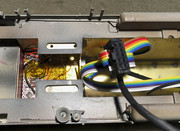
The motivation for all this was to facilitate the easy and complete disconnection of the locomotive shell from the frame. It works because there is enough headroom for the IDC connector. So the main point was the connector, not the ribbon cable. Otherwise many wires can be easily herded using un-shrunk heat shrink tubing.

As for resistors, should you use an ESU decoder, each of the function outputs (all full-power on the L decoders) have a 32-level PWM dimmer. Finding just the right resistor value becomes a lot less critical. With today's LEDs a 1K for a pair of 3mm headlights in series should be more than bright enough. For ground lights, the now-unobtanium LED Baron 0402s from Germany would work great with 10K (wish I had ordered more!) For ground light fixtures, these are available from a seller who uses Shapeways. I think one could use an LED as large as 0603 in them. On my brass engines I'm starting to do root canals on the cast brass fixtures with 1 or 0.8mm ball-end carbide dental bits.

Here's a top view showing the 10 pin header on the far right. The PCB next to the decoder manages track pickup and motor wires. The diode is a 1500 watt bipolar TVS (transient voltage suppressor) across the rails to protect the decoder from voltage spikes caused during short circuits.


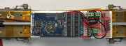
Not shown, there is also a 2 pin Swiss machine connector that connects the speaker to the decoder that can be seen in the photo in a previous post that shows the speaker. There is also a 4-pin polarized connector on the PC board that connects to an external 10 Farad ESU Power Pack. The new 5L decoders now have built-in 2 Farad Power Packs.

As for resonance above the passive radiator, don't sweat it. Typically in our engines a cavity resonance is at or above 1 kHz. The passive really doesn't put out anything up there.

Honestly, I wouldn't bother with an etched radiator. The % open area is critical. Can you get that up to 75%? Whatever is there, it needs to be acoustically transparent. Letting the front fan opening breathe can also help a lot.
« Last Edit: February 05, 2022, 10:36:04 PM by Bob »