After assembling one of the lighting blocks I quickly realized that having so many loose wires coming out of the back was
not going to be fun to solder to a small prototyping "relay" board on which the dropping resistors were mounted. For one locomotive that might be OK. But I have a bunch of GP9s to build and David has a small fleet. Hmm... back to the drawing board?
While feeling frustrated I saw a post by Mike DeBerg on O Gauge Railroading showing the interior of his new 2 Rail SD40-2 from Sunset. That was the cleanest DCC install I've seen.
https://ogrforum.com/topic/sunset-models-3rd-rail-sd40-2-an-inside-lookSunset designed a new daughter board for the ESU 5L decoder. That custom board uses a bunch of JST XH connectors for wire management. A real incandescent light bulb turned on in my head... Why not have some custom PC boards made that could attach to the back of a lighting block?
From US vendors prototype quantities of PC boards can be quite expensive. Many 3D printing channels on Youtube are sponsored by a Chinese company out of Hong Kong, JLC PCB. I uploaded Gerber files from KiCad and got a quote for only $2 for 30 boards, including a $6 new customer discount. Including shipping the cost per board was less than $1.
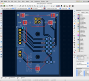
I downloaded the current (and free!) KiCad software for schematic capture and PC board layout. It did not take long to arrive at a PC board design. That said, soldering the LEDs to the board would require reflow soldering, something I've never done at home.
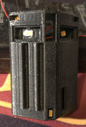
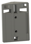
The lighting block was also modified to have open apertures for PC mounted LEDs. The two central mounting holes are sized for M2 threaded inserts.
Soldering tiny wires to the back of many surface mounted LEDs is not all that difficult. But how can one solder the LED to a PC board when the contacts are hidden on the bottom of the package? That requires reflow soldering, in which a paste of solder and flux is applied to the PC board pads and the LEDs are set into the paste. Then the entire assembly either goes into a reflow oven (at a commercial facility) or at home on top of an inexpensive digitally controlled hot plate.
I bought a cheap digital hot plate from Amazon and in an afternoon reflow soldered 5 LEDs to each of the 30 prototype boards.
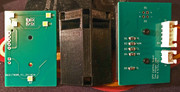
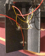
Here are a sample of the results. On the left, one of the reflow boards with 5 SMT LEDs. Center, a modified lighting block with clear apertures for LEDs mounted to the PC board. Right, the back of the PC board with a pair of JST connectors. The upper one connects back to the decoder board. The lower connector powers ground (truck) lights, if used.