Author Topic: Red Caboose GP9 remotor  (Read 5507 times)

Bob

  • Global Moderator
  • Full Member
  • *****
  • Posts: 162
    • Bob's web site
Re: Red Caboose GP9 remotor
« Reply #15 on: March 23, 2024, 08:45:49 AM »
Getting back to motors, we just saw proof of the quality of a Portescap coreless motor on the A&O. Craig's Overland GP35 died with a shorted Pittman 8313 motor, which also destroyed the V4L decoder. Over the past few weeks Craig installed an eBay Portescap in his unit using 3D printed parts he designed and shaft couplers I turned on the lathe. He also plugged a new 5L DCC decoder into the carrier board.

Yesterday Craig ran it on the A&O, both light and with a 14 car train upgrade and downgrade. With default ESU 5L motor parameters it ran perfectly smoothly, better than any other locomotive on the A&O. The minimum speed was so slow it was almost impossible to tell it was moving. We opted to program an increase in the minimum speed because it was impractically slow.

Operation was nearly silent, with only a faint hum from back-EMF sampling. Curiously all this was with the default BEMF motor parameters that came in the sound file. We only changed CVs 2, 5 and 6.

The engine should run a lot cooler. The new motor produces 1.8 times more torque per Ampere than the Pittman 8x13. The stall current is only 1.2 A, so it can be used with an ESU HO decoder.

Everybody agreed that this was a roaringly successful transplant.

Craig

  • Jr. Member
  • **
  • Posts: 68
    • Rio Grande 3rd Division
Re: Red Caboose GP9 remotor
« Reply #16 on: March 23, 2024, 11:07:45 AM »
As Bob stated..”Many smiles were had!”  Hehehehe

The new motor exceeded my wildest expectations I have to say. The normal operating speed may throw folks for a loop for a while…but the engine is just an amazing puller!  And hardly any motor whine.

Even more sad though…I didn’t record anything going UP grade…just down.

DOH!   :)

Looking forward to seeing what the operators think next weekend!
Craig
A&O Track and Electrical Crew

Bob

  • Global Moderator
  • Full Member
  • *****
  • Posts: 162
    • Bob's web site
Re: Red Caboose GP9 remotor
« Reply #17 on: March 23, 2024, 06:49:19 PM »
Craig -
When you are not dispatching on Saturday and your brother Mark sits on the "throne" you deserve a chance to run your GP35 on the head of a manifest train.

Here's a comparison between the Pittman 8x14 (Weaver, P&D), 8x13 (Overland) and Portescap. If you click on the chart and it looks funny, click again. PostImage is throwing a hissy fit when initially enlarging the JPG image.


Back to 3D CAD, Big Train James suggested trimming the inside of the Red Caboose walkways so that the speaker can be inserted from the bottom. That would permit the dynamic brake blister to be glued in place. So here's a fixture to hold the walkway assembly in the mill for trimming.


The 3D print came out great and fits like a glove. Overhangs on the bottoms of the two channels are not beautiful (it was printed upside-down) but that doesn't matter. The two holes are for bolting down flat aluminum strap clamps to hold the walkway firmly against the top of the fixture.

The white hazy deposit on the center of the fixture is stick glue that was applied to the QIDI textured build plate. It can be washed off with soapy water if desired.


Next I need to design the 2-piece speaker mounting clips. Why all this effort? With a bunch of models to build, time spent now should make the assembly line run a lot faster. That's my story and I'm sticking to it.


Bob

  • Global Moderator
  • Full Member
  • *****
  • Posts: 162
    • Bob's web site
Re: Red Caboose GP9 remotor
« Reply #18 on: March 25, 2024, 08:01:36 PM »
Sometimes 3D printing can be cheaper than subtractive machining alternatives. The fixture in my last post cost about $1 in filament. I priced various plastics and aluminum stock from which the fixture could be milled, and always came up with about $30 in raw material. Of course I have to do a lot more printing to amortize the cost of the printer itself.

Using DesPlaines brass frames means losing some of the under frame details present in the OEM plastic frame. Those details were not accurate, but they are very hard to see. To help fill the void I printed some half-frame details since a nearly 12" long part exceeds my printer's build volume.


RickBacon

  • Jr. Member
  • **
  • Posts: 86
Re: Red Caboose GP9 remotor
« Reply #19 on: March 26, 2024, 09:13:09 AM »
Hey Bob!
I'm pretty excited about Craig's success with the smaller motor.  Do we have a full part number for the motor.  I've been digging through Portescap's website and catalogue but haven't found the exact motor.  It seems the 216E number is a suffix to the part number, but I haven't figured out what it indicates.  By matching the specifications you tabled, I might be able to figure it out, but I still have several hundred more individual spec sheets to compare!  Is Craig's example a single ended shaft, or double?

3D printing is definitely changing the landscape of model building! 
   
Rick Bacon
Windsor, CO

Bob

  • Global Moderator
  • Full Member
  • *****
  • Posts: 162
    • Bob's web site
Re: Red Caboose GP9 remotor
« Reply #20 on: March 26, 2024, 10:13:26 AM »
Rick -

The motor is a custom unit, military surplus. 216E specifies a 12 Volt 10 Ohm winding. It has a double shaft, but curiously one end is 3mm and the other end 2mm diameter. Mounting screws are normally metric but this one was tapped 4-40.

At the moment the listing has disappeared from eBay. The seller was Elimia Industrial. They sold for $37 each in single quantity. I found a stock motor from an industrial supply house in England, but the price was about $200 USD.

Bob

  • Global Moderator
  • Full Member
  • *****
  • Posts: 162
    • Bob's web site
Re: Red Caboose GP9 remotor
« Reply #21 on: March 26, 2024, 07:01:52 PM »
Rick -
I procured the FDM printer to make structural parts, primarily inside models, but also for custom fixturing for my Sherline mill and lathe. Most of my prints are extruded in ABS.

The GP9 under-frame detail rails are hard to see, so I won't try to hide layer lines and printing artifacts. For the most part they just fill a visible gap between the trucks and the frame that may be observed as the locomotives cross over the Ohio River bridge.

As I grow in my Fusion CAD skills, I wonder if a resin printer might be in my future...

Big Train James

  • Newbie
  • *
  • Posts: 19
Re: Red Caboose GP9 remotor
« Reply #22 on: March 27, 2024, 11:28:34 AM »

With the printed blocks I will have to carefully trim the length of brass grab irons so that they don't extend past the inside wall of the shell.

I've just been re-reading this thread.  Could you not leave some voids in the light blocks to account for grab iron penetration?  You could do blind holes, or full depth, and you could do holes for each leg of each grab, or a slot per grab that accounted for both legs.  Some precision would be prudent for the top two grabs near the numberboard and class light openings, but the rest could be generously sized to allow plenty of room for penetrating wire and glue blob.

Jim

Bob

  • Global Moderator
  • Full Member
  • *****
  • Posts: 162
    • Bob's web site
Re: Red Caboose GP9 remotor
« Reply #23 on: March 27, 2024, 08:41:02 PM »
That can be done for some grabs and other brass fittings, but not all. The top two end grabs have to be trimmed. There is very little plastic thickness between the cutout for the headlight LEDs and the number board cavity. Light leaks must be avoided.

On the roof some of the lift rings are not critical but others may need to be flush to avoid tearing the speaker during insertion and removal. By the way, the kit plastic lift rings (and some brass ones we received from Bill McClung) are undersize. Attached is a photo of a GP7 being cut up in Loveland. The P&D brass parts (now out of stock) are the correct size, but can be difficult to cut.


Big Train James

  • Newbie
  • *
  • Posts: 19
Re: Red Caboose GP9 remotor
« Reply #24 on: March 28, 2024, 12:03:53 PM »
Hi Bob,
I have another pair of questions regarding the re-motor project.  I hope I don't tire you out tugging on your sleeve all the time.  ;D

I notice in your motor comparison matrix that the Portescap motor has a significantly lower no-load speed than either Pittman option.  Presuming that gear reduction remains the same without regard to choice of motor, does the lower top end speed present any issues for you?  I recognize that we seldom run our models as fast as they could go, so I suspect it's not a problem.

In a different context, where reduction is not predetermined, the no-load or rated speeds do affect a final gear ratio, which in turn affects torque.  It's been a bit of a balancing act as I seek a suitable motor for my switcher project.  It seems that many of the better quality motors have substantially lower no-load speeds compared to the Pittmans.

The second question is in regard to the use of an HO decoder, in particular one of the ESU Loksound variety.  Do the HO decoders have enough power to successfully feed the Tang Band modules?  Or to power a TB module and a smaller driver for the bell and horn, as I believe they have two speaker outputs.  Also, the large format Loksound decoders have onboard keep-alives now.  Are they integral or separate on the HO versions.  It would be nice to use an HO decoder for space and cost, although some of that may be offset if a separate keep-alive is required.

Jim

Big Train James

  • Newbie
  • *
  • Posts: 19
Re: Red Caboose GP9 remotor
« Reply #25 on: March 28, 2024, 12:07:04 PM »
Coincidentally, I just measured EMD lift rings while at the Illinois Railway Museum during the Chicago meet.  The ones I measured were on an sd40-2, but they appear to be the same as the one in your photo.  I'm planning on having some brass castings done within the next month or two.  I'll share results when I have them.

Jim

Bob

  • Global Moderator
  • Full Member
  • *****
  • Posts: 162
    • Bob's web site
Re: Red Caboose GP9 remotor
« Reply #26 on: March 28, 2024, 06:58:58 PM »
Jim -

I'm glad you are participating on this thread! You have helped me break out of some mental blocks and arrive at better solutions, for which I am appreciative.

I'm in no way concerned about insufficient top speed with the Portescap motor. In fact I still plan to change the P&D 15:1 reduction to 25:1 reduction. That should multipliy the motor torque by about 1.6, although I do not anticipate lack of torque to be an issue. It will, however, reduce the average motor current.

The A&O isn't a racetrack display layout. It is for guys who like to operate. Although it is in a huge basement, running fast on the mainline and getting to the next "town" in a matter of seconds doesn't satisfy and would be an undue stress on the dispatcher. Most trains do switching, and for that smooth low-speed control is preferable.

What top speed is appropriate for your models depends on how you want to run them. The Reading ran a lot of SW "pups" in mainline coal hauling. On the other hand, GCOR limits the top yard speed to 10 MPH, although many modelers run faster than that, seemingly trying to pop a wheelie when accelerating from a stop. When when stopping, they stop on a dime, which sometimes may unfortunately be in the brakeman's pocket.

I anticipate that the larger HO decoders, such as the 58240, should be able to handle the motor current. The thinner height opens a lot of possibilities.

I also don't expect the less powerful amplifier in an HO decoder to be an issue. Our ears respond to increases in SPL in a logarithmic fashion, so a 3W amp isn't 3X as loud as a 1W amp.

The keep-alive is a consideration. ESU sells good 3-wire PowerPacks. The small one has a single 1 Farad capacitor. The 5L decoder has two 1 Farad capacitors. The large PowerPack has two 5 Farad capacitors. But sometimes the longest run time isn't the best. How much trouble can a derailed locomotive get into in only 4 seconds? Can it meet our nemesis gravity?

As for lift rings, glad to hear your SD40-2 measurement matches. Also note that the cast base or washer of the lift ring is of a large diameter. For a while I was concerned that the P&D lift rings were about 30 thou in diameter, but that's about not oversize. If anything it is undersize.

Bob

  • Global Moderator
  • Full Member
  • *****
  • Posts: 162
    • Bob's web site
Re: Red Caboose GP9 remotor
« Reply #27 on: May 21, 2024, 01:42:03 PM »
One thing I've been obsessing over is how to improve and illuminate the Red Caboose GP9 number boards. The OEM polycarbonate inserts are nearly impossible to install and they are far thicker than the shell. They can stick out on both the inside and outside of the shell cutout. That's light leak city. Harrumpf.

One thought was to mill a brass cutting template for a thin clear styrene number board, but that would be likely to leak light around imprecisely cut edges and raised the problem of how to mount it in the shell.

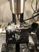
I decided to just go for it and clamped an OEM insert in the Sherline mill. Two parallels and a spacer raised it up in the vise with just the thinnest bit of the edge clamped. Too much grip on the vise could crack the part, but too little might let it fly out and be ruined.

Fortunately, with light 10 thou passes I was able to thin the boards without dislodging them and to a final dimension less than the thickness of the shell. A sharp Niagara end milll wider than the board left a super smooth but nice frosty finish, perfect for diffusing light.


A couple swipes with a fine file on the outer sharp bevel edge added a very slight bevel that made pressing the insert in place simply and easy to adjust. I think I will install the flat milled side to the outside and sand the inside to be a secondary diffuser.

One thing I noticed is that since plastic shrinks when it cools from a liquid, the centers of the number board castings were not flat but slumped a bit. That suggests that both sides should receive a cut to make sure they are flat.

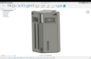
The lighting block for each end has also been refined a bit. There is a rabbet around the number board LED cavities for installation of a thin 0.010 styrene tertiary light diffuser. Also there is now a tab on the top for a small PCB board to aggregate the various LED wires to a single 5 wire harness going to the decoder. The PCB will be underhung to the tab with double stick tape. The wires are planned to be 30 AWG solid kynar wire wrap wire, which can hold its shape once formed, to a 2.5mm pitch JST XH connector.


A random thought: At least on some later EMD GPs, each number board had 3 incandescent lamps inside. Particularly on B&O engines I saw as a child, the number boards were translucent and one could see the hot spots of each bulb. What if I drilled 3 shallow holes on the inside of the inserts? Could that effect be effectively emulated?

Thoughts?

coaltrain

  • Newbie
  • *
  • Posts: 16
Re: Red Caboose GP9 remotor
« Reply #28 on: August 15, 2024, 12:18:02 PM »
I did a video on 3D printing weight molds for my shay locomotives.  I print the molds in PLA, place them in a container of ice water, then pour in the cerrobend metal, then cut away the mold.  what I did not show in the video is that I actually pour in a small amount of cerrobend and then drop in lead pieces, then fill in more cerrobend to fill in all the gaps.  This lessens the amount of cerrobend I need and I think makes the weight even heavier.

Bob

  • Global Moderator
  • Full Member
  • *****
  • Posts: 162
    • Bob's web site
Re: Red Caboose GP9 remotor
« Reply #29 on: August 15, 2024, 08:35:50 PM »
Great idea to drop lead chunks in the cerrobend. Thanks for the tip, Jeff.