Author Topic: New drive train for "Buster" the Overland C630  (Read 2627 times)

Bob

  • Global Moderator
  • Full Member
  • *****
  • Posts: 162
    • Bob's web site
New drive train for "Buster" the Overland C630
« on: March 05, 2022, 01:19:15 PM »
Because it has been too slow on the forums, I thought I'd toss some of my recent machine shop pasta against the wall to see if any sticks. To be clear, I'm not a real machinist, nor do I play one on TV, but I have been noodling on a Sherline mill and lathe for almost 20 years. That said, I'm no Jay Criswell!

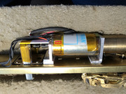
Back in the A&O 1.0 days I bought an early Overland Alco C630 on eBay. This was a troubled spirit that has plagued me for nearly 2 decades. After installing an NCE 408 decoder I uncovered that some jack-rabbit starts were caused by extreme cogging in a Sagami (or Salami) motor. That had to be replaced. I was a beginner hack on the mill but still managed to get a suitable Pittman 8514 installed along with a new brass flywheel. It was crude but worked, made from aluminum from Ace Hardware and NWSL universals.


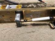
The next problem was that one (or both) of the tank drive universals kept blowing apart. Most of the gear ratio is in the gear tower, so the shafts get a lot of torque. These were bizarre designs like two pairs of cupped hands grabbing hold of a ball bearing. They didn't stay together, and when they did, created a lot of backlash. Here we see one intact OEM drive shaft after the other one blown was removed.


After much study I hoped I could make a new pair of drive shafts using P&D parts. I'd need to make brass adapters to attach to the 3mm shafts and translate to P&D universal parts.

The gear tower output shaft and axle gearbox input shaft were both 3mm. After measuring the OEM diameters I set out to make some adapters.

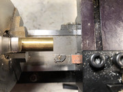
First up, for an accurate center hole we need to face off the rough end of brass stock. We must have an accurate tool post height to avoid leaving a "nubbin" that would interfere with drilling.


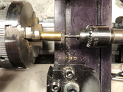
To get an accurately centered hole, I first use a spotting drill. This not only locates hole center, but adds a bevel to guide a drill bit to an accurate start.


Let's save here and move to part 2.

Bob

  • Global Moderator
  • Full Member
  • *****
  • Posts: 162
    • Bob's web site
Re: New drive train for "Buster" the Overland C630
« Reply #1 on: March 05, 2022, 01:31:56 PM »
Part 2.

Quality drill bits are great, but they usually drill an oversize hole. Oversize = wobble. A better way is to drill an undersize hole then run a chucking reamer in the lathe tailstock.


It is important to realize that when machining everything flexes. Small machined parts do. So does the machine, and the carriage and... Bring the parts to a close tolerance then finish them off with a light touch, in this case, with a chucking reamer.


With an accurately drilled hole, on to part 3.

Bob

  • Global Moderator
  • Full Member
  • *****
  • Posts: 162
    • Bob's web site
Re: New drive train for "Buster" the Overland C630
« Reply #2 on: March 05, 2022, 06:38:24 PM »
Part 3.

With an accurately-sized 3mm hole, we can profile the coupling part, the major diameter matching the OD of the P&D universal, and minor diameter to be a just slip-fit into that part.


That leaves us with the first of four of these. The part fits fine but is a bit long and a nubbin left from parting off needs to be cleaned up.


Each of the 4 couplers needs to be cross-drilled and tapped to accept 2mm set screws. For that I brought out the mill rotary table in an angle holder, and the Sherline collet holder. Here I'm locating the hole prior to cross-drilling. The big nut above the drill chuck is sometimes known as a "thread saver" but I made it to apply pressure  to remove chucks from Sherline's Morse 2 taper without any need to pound on the spindle drawbar. Banging on the drawbar can easily throw the mill out of tram (square) and if excessive, damage the spindle bearings.


After drilling we can tap the threads. The part is small and would be difficult to hold by hand if removed from the collet, so I went ahead and cut the threads while still on the mill. Since I don't have an M2 bottoming tap, I drilled clear through the part so that a regular tap could run all the way through.


« Last Edit: March 05, 2022, 07:35:23 PM by Bob »

Bob

  • Global Moderator
  • Full Member
  • *****
  • Posts: 162
    • Bob's web site
Re: New drive train for "Buster" the Overland C630
« Reply #3 on: March 05, 2022, 06:49:01 PM »
Part 4.

A larger collet holds the coupler in the mill so that it and a P&D large universal "helmet" can be drilled prior to being pinned. Here a 1/16" drill is about to go all the way through the assembly. The Delrin part is loose and can spin, but with everything aligned it doesn't budge.


Starting a 1/16" spring pin can be tricky. While the universal and coupler holes are in alignment, I found that I could hold the pin in the mill Jacobs chuck and drive the Z axis down to insert the pin in the Delrin and bump it against the brass to keep things aligned. Then I loosened the chuck, raised Z and removed the assembly from the collet.


After removal it was an easy matter to press the pin in place using a cheap Horrible Freight press and a bench block (sorry for the blurry photo.)

On to part 5.


Bob

  • Global Moderator
  • Full Member
  • *****
  • Posts: 162
    • Bob's web site
Re: New drive train for "Buster" the Overland C630
« Reply #4 on: March 05, 2022, 07:06:45 PM »
Part 5.

P&D sells a nice 2 piece slip-fit coupling that allows the drive shaft to lengthen around a curve or shorten when straight. The one needed here is for the "lower" drive shaft insert which can accept a metal drive shaft extension.  Normally this would be a steel rod with straight knurled ends to be driven into the Delrin part. I'll use a tight-fit turned brass shaft and pin them together. Curiously, the large universal "helmet" has a 0.144" diameter hole but the lower drive shaft part measures 0.12 something. No problem, easy to do on the lathe. The OAL of the shaft is 0.62". After turning to initial diameter I broke the corner with a file and test-fit the part to prove it was snug.


Cross drilling and pinning the universal was easy using a collet, not shown. But a collet could not hold the expansion part. What to do? For the first time I used my small 4 jaw scroll chuck. This allowed me to clamp the universal without hitting the spring pin. Truth be told I hand-held the end of the Delrin part while drilling to make sure it didn't sag. It was long enough to keep my fingers out of potential trouble.


To part 6.

Bob

  • Global Moderator
  • Full Member
  • *****
  • Posts: 162
    • Bob's web site
Re: New drive train for "Buster" the Overland C630
« Reply #5 on: March 05, 2022, 07:11:22 PM »
I love it when a plan comes together. Here is the new drive train after assembly.


So how can we measure the inside diameter of the various P&D parts? A cheap set of plug gages comes to the rescue. These are precision ground pins in a set incrementing in 0.001" diameters.


That's my story, and I'm sticking to it.


Bob

  • Global Moderator
  • Full Member
  • *****
  • Posts: 162
    • Bob's web site
Re: New drive train for "Buster" the Overland C630
« Reply #6 on: March 05, 2022, 07:14:51 PM »
Sources of materials for the project:

P&D Hobby Shop for drive train parts.

Sherline for excellent miniature lathes, mills, and accessories.

McMaster-Carr for machining supplies including reamers and set screws.

Ace Hardware for 1/4" brass rod (alternatively Online Metals.)

Buster will be a welcome addition for RockyOp 2022.
« Last Edit: March 06, 2022, 05:26:40 PM by Bob »

RickBacon

  • Jr. Member
  • **
  • Posts: 86
Re: New drive train for "Buster" the Overland C630
« Reply #7 on: March 07, 2022, 09:42:47 AM »
Amazing work Bob; elegant and straight forward solution! The mothership fleet is in vary capable hands! 
Rick Bacon
Windsor, CO

Bob

  • Global Moderator
  • Full Member
  • *****
  • Posts: 162
    • Bob's web site
Re: New drive train for "Buster" the Overland C630
« Reply #8 on: April 09, 2022, 07:29:18 PM »
Thanks, Rick, for your kind comment.

Buster is getting a temporary decoder install. I say temporary because I'm not yet installing the full lighting package, waiting until it is fully painted. For now, it will only have headlights at each end. No class, number board, walkway or a single ground light. It should be ready for the pre-Rocky Op shakedown session.

Unlike later Overland Alcos, the radiator intakes are solid castings instead of prototypical stamped slotted brass sides that make great sound outlets. The sound has to come out through holes I drilled in the frame. After some puzzling it was clear that a large Tang Band 1931S module would fit sideways in the locomotive shell. It is attached with Velcro, which conforms to the non-uniform car body side. That causes it to mount at a slight angle. A block of urethane foam wedges it in place and keeps it from rattling.


As for RockyOp, there will be 3 new road engines, a C&LS RSD12, an Oriental C420, and Buster the C630.

By the way, a C630 has an AC alternator instead of a DC generator. Unlike a generator, you can't just hook up an alternator to batteries and get it to run as an electric motor to start the engine. Instead, a C630 has a third air tank to run an air start turbine. Vroom at startup.

There is a great video on You'reCensored of the DL starting a 6 axle engine at Steamtown PA. The hostler opens a door behind the cab, sits on the handrail and puts his feet inside the engine compartment. Vroom then lots of 16 cylinder 251 bass goodness.

Edits: fixing typos.
« Last Edit: April 09, 2022, 07:58:58 PM by Bob »

Craig

  • Jr. Member
  • **
  • Posts: 68
    • Rio Grande 3rd Division
Re: New drive train for "Buster" the Overland C630
« Reply #9 on: April 11, 2022, 02:22:45 PM »
Heheheh. Buster. I like it.
Craig
A&O Track and Electrical Crew

Big Train James

  • Newbie
  • *
  • Posts: 19
Re: New drive train for "Buster" the Overland C630
« Reply #10 on: April 11, 2022, 03:04:57 PM »
I'm curious about the orientation of the speaker module on edge.  I know it's always said that bass isn't directional, but I intuitively feel like the sound may not end up going where it's wanted most, if the speaker is mounted like that.

Or is it more a matter of where the holes are located, through which the the sound escapes the shell?  Always curious about this stuff.

Jim

Bob

  • Global Moderator
  • Full Member
  • *****
  • Posts: 162
    • Bob's web site
Re: New drive train for "Buster" the Overland C630
« Reply #11 on: April 11, 2022, 05:52:13 PM »
Jim -

I wouldn't normally choose to mount the speaker on edge, but the particulars of this install suggested it might just work. The shell is pretty much solid with no sound coming out except through a couple of tiny screens and the exhaust stack. So I drilled a bunch of prairie dog holes in the frame.

Sound will eventually find its way out through the frame floor. Some needs to thread its way around the hollow fuel tank but more can exit above the trucks.

The speaker cone is buried in the back of the shell, only a short distance from the opposing side wall That's not ideal, and may produce a resonant peak in the upper midrange. Locating the passive radiator closer to the frame holes may favor bass reproduction.

Anyway, the 1931S produces more bass than the 1925S. This is all a guess, no guarantees. No film at 11:00.

Bob