Recent Posts
61
Member Projects / Re: Red Caboose GP9 remotor
« Last post by Bob on March 11, 2024, 06:27:59 PM »Back to the original topic: remotor, and including some benefits.
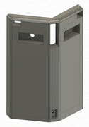
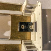
The effort to install a new, smaller motor in my RC GP9s comes with a benefit to increase headroom inside the shell. This afternoon I milled a TB1935 module to make it narrower, only 1.3." I narrowed it as far as I felt comfortable while holding it in a Sherline vise. It now slips easily in a new RC GP9 shell. So far so good. There are a couple of pinhole leaks in the enclosure, due to voids during injection molding, but not enough to significantly influence bass response. It does, however, now equalize changes in barometric pressure.
Soon a difficulty became apparent. The dynamic brake blister is narrower inside than the shell itself. Rut roh!
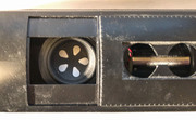
Plan A: The DB part has not been assembled, so there are two slots for the exhaust stacks that could be used to hold it in a fixture for milling. That wouldn't be too difficult but the result would be a part that loses the alignment "lip" and reduces the amount of gluing surface. A strong joint is desired because most operators will pick up the finished locomotive by the DB blisters when re-raining after an "oopsie." Stuff happens.
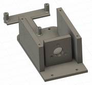
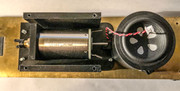
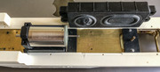
Plan B: After careful measurement I discovered that I had about 0.2" of clearance between the bottom of the speaker and the top of the new motor mount. Originally I planned to center the driver in the DB fan opening, with the passive radiator situated towards the back of the long hood. That wouldn't work since it would interfere with the rear drive tower. However, it can be flipped around 180 and still leave some room for wires.
Either way, I still plan for the primary weight to be Cerrobend poured into the bottom of the OEM fuel tank maybe with the fuel tank taped to the bottom of a pot filled with cold water. The new brass frame also helps.
The effort to install a new, smaller motor in my RC GP9s comes with a benefit to increase headroom inside the shell. This afternoon I milled a TB1935 module to make it narrower, only 1.3." I narrowed it as far as I felt comfortable while holding it in a Sherline vise. It now slips easily in a new RC GP9 shell. So far so good. There are a couple of pinhole leaks in the enclosure, due to voids during injection molding, but not enough to significantly influence bass response. It does, however, now equalize changes in barometric pressure.
Soon a difficulty became apparent. The dynamic brake blister is narrower inside than the shell itself. Rut roh!
Plan A: The DB part has not been assembled, so there are two slots for the exhaust stacks that could be used to hold it in a fixture for milling. That wouldn't be too difficult but the result would be a part that loses the alignment "lip" and reduces the amount of gluing surface. A strong joint is desired because most operators will pick up the finished locomotive by the DB blisters when re-raining after an "oopsie." Stuff happens.
Plan B: After careful measurement I discovered that I had about 0.2" of clearance between the bottom of the speaker and the top of the new motor mount. Originally I planned to center the driver in the DB fan opening, with the passive radiator situated towards the back of the long hood. That wouldn't work since it would interfere with the rear drive tower. However, it can be flipped around 180 and still leave some room for wires.
Either way, I still plan for the primary weight to be Cerrobend poured into the bottom of the OEM fuel tank maybe with the fuel tank taped to the bottom of a pot filled with cold water. The new brass frame also helps.