Recent Posts

Pages: 1 ... 4 5 [6] 7 8 ... 10
51
Member Projects / Re: Red Caboose GP9 remotor
« Last post by Bob on March 25, 2024, 08:01:36 PM »
Sometimes 3D printing can be cheaper than subtractive machining alternatives. The fixture in my last post cost about $1 in filament. I priced various plastics and aluminum stock from which the fixture could be milled, and always came up with about $30 in raw material. Of course I have to do a lot more printing to amortize the cost of the printer itself.

Using DesPlaines brass frames means losing some of the under frame details present in the OEM plastic frame. Those details were not accurate, but they are very hard to see. To help fill the void I printed some half-frame details since a nearly 12" long part exceeds my printer's build volume.


52
Member Projects / Re: Red Caboose GP9 remotor
« Last post by Bob on March 23, 2024, 06:49:19 PM »
Craig -
When you are not dispatching on Saturday and your brother Mark sits on the "throne" you deserve a chance to run your GP35 on the head of a manifest train.

Here's a comparison between the Pittman 8x14 (Weaver, P&D), 8x13 (Overland) and Portescap. If you click on the chart and it looks funny, click again. PostImage is throwing a hissy fit when initially enlarging the JPG image.


Back to 3D CAD, Big Train James suggested trimming the inside of the Red Caboose walkways so that the speaker can be inserted from the bottom. That would permit the dynamic brake blister to be glued in place. So here's a fixture to hold the walkway assembly in the mill for trimming.


The 3D print came out great and fits like a glove. Overhangs on the bottoms of the two channels are not beautiful (it was printed upside-down) but that doesn't matter. The two holes are for bolting down flat aluminum strap clamps to hold the walkway firmly against the top of the fixture.

The white hazy deposit on the center of the fixture is stick glue that was applied to the QIDI textured build plate. It can be washed off with soapy water if desired.


Next I need to design the 2-piece speaker mounting clips. Why all this effort? With a bunch of models to build, time spent now should make the assembly line run a lot faster. That's my story and I'm sticking to it.

53
Member Projects / Re: Red Caboose GP9 remotor
« Last post by Craig on March 23, 2024, 11:07:45 AM »
As Bob stated..”Many smiles were had!”  Hehehehe

The new motor exceeded my wildest expectations I have to say. The normal operating speed may throw folks for a loop for a while…but the engine is just an amazing puller!  And hardly any motor whine.

Even more sad though…I didn’t record anything going UP grade…just down.

DOH!   :)

Looking forward to seeing what the operators think next weekend!
54
Member Projects / Re: Red Caboose GP9 remotor
« Last post by Bob on March 23, 2024, 08:45:49 AM »
Getting back to motors, we just saw proof of the quality of a Portescap coreless motor on the A&O. Craig's Overland GP35 died with a shorted Pittman 8313 motor, which also destroyed the V4L decoder. Over the past few weeks Craig installed an eBay Portescap in his unit using 3D printed parts he designed and shaft couplers I turned on the lathe. He also plugged a new 5L DCC decoder into the carrier board.

Yesterday Craig ran it on the A&O, both light and with a 14 car train upgrade and downgrade. With default ESU 5L motor parameters it ran perfectly smoothly, better than any other locomotive on the A&O. The minimum speed was so slow it was almost impossible to tell it was moving. We opted to program an increase in the minimum speed because it was impractically slow.

Operation was nearly silent, with only a faint hum from back-EMF sampling. Curiously all this was with the default BEMF motor parameters that came in the sound file. We only changed CVs 2, 5 and 6.

The engine should run a lot cooler. The new motor produces 1.8 times more torque per Ampere than the Pittman 8x13. The stall current is only 1.2 A, so it can be used with an ESU HO decoder.

Everybody agreed that this was a roaringly successful transplant.
55
Member Projects / Re: Red Caboose GP9 remotor
« Last post by Bob on March 16, 2024, 05:35:57 PM »
A Red Caboose GP9 dynamic brake got hammered this afternoon. The printed fixture worked fine, although clamping in the vise needed to be gentle because printed ABS is not as rigid as aluminum.

Curiously, the styrene objected to conventional milling, but was fine with climb milling. It required light cuts and there was considerable spring back.

Here it is fresh off the mill, still in the fixture.


56
Member Projects / Re: Red Caboose GP9 remotor
« Last post by Bob on March 16, 2024, 03:17:48 PM »
Sometimes when you have a hammer, every problem looks like a nail.

The alternative of milling the inside of the dynamic brake blister seems the most attractive. This morning I designed and printed a fixture to firmly hold the blister upside-down in the Sherline mill. Work holding is accomplished by a pair of 4-40 screws that pass through the oval cutouts for the exhaust stacks.

57
Member Projects / Re: Red Caboose GP9 remotor
« Last post by Bob on March 13, 2024, 06:51:06 PM »
Jim -

Why Cerrobend? Actually, lead shot randomly packed is only 77% as heavy as cast Cerrobend (Wood's metal). The space between round balls must be factored in, although it would be partially filled with epoxy or other less-dense glue.

According to Wikipedia, a random packing of loose balls in a cavity only fills about 63.5% of the volume. The density of lead is greater than Cerrobend, 11.34 g/cm^3 vs 9.4 g/cm^3, but the advantage is lost due to the low packing density.

Grades on the A&O are steep, and we need all the tractive effort we can get.

As for the DB interference, I'm leaning towards making a fixture and milling it out so that the full height above the motor mount is available for electronics. There's a big winter storm heading my way and that might be a good snow day project.

So far I've found FDM 3D printing to be liberating. It lets me imagine new answers to problems that would have been tedious if built-up in styrene or machined on the mill. So far the primary limiters are my imagination and NOOB learning curve with Fusion 360.

The light package mounting block is a variation of an idea I had decades ago for the long hood of an Overland GP30 or 35 (don't remember which.) Back then I got a block of Sculpey modeling clay and packed it in the end of the shell. Then I carved out openings for the various LEDs (all hand-colored blue meanies) and incandescent headlights, also enlarging holes for the various grab irons that poked inside. After sculpting the block was hardened by baking in the kitchen oven.

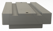
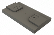
With the printed blocks I will have to carefully trim the length of brass grab irons so that they don't extend past the inside wall of the shell.

I'm substituting brass detail parts including the handrails, grabs and lift rings since those are delicate and easily broken (the plastic lift rings are far undersize.) The A&O is all about operating sessions, so some innocent but ham-fisted handling of equipment must be anticipated.

All the best,
Bob
58
Member Projects / Re: Red Caboose GP9 remotor
« Last post by Big Train James on March 11, 2024, 09:14:23 PM »
Bob,
I'm curious why you are intent on using Cerrobend for the weight.  I've got a similar situation with the fuel tank for my switcher, and I'm planning on filling it with lead shot set with epoxy.  I suppose the space between the round balls will add up to some incremental weight, but I can't see it being enough to make a difference. 

If you want the weight to be removable in the future, could you spray the fuel tank with mold release before filling with the lead shot and epoxy?  You could then theoretically have a weight that is fitted perfectly to the tank, but is not bonded to it directly.

I never thought about the dynamic brake blister when figuring the size for milling the speaker enclosure. :o ::)  However, to be fair I had always intended to develop a different drive that was much lower profile than the stock version, so I would have room for the speaker anywhere inside the long hood as long as the width worked.

The insert to hold the various lights in hood end is a great example of what 3d cad and printing can do for us.  Yes, you could build the equivalent from styrene sheet or other material, but the 3d printed version is probably a much easier solution, yielding better results.  And there's no contest short of resin casting when it comes to repeatability if you need multiples.  It's a great tool for so many applications.

Jim
59
Member Projects / Re: Red Caboose GP9 remotor
« Last post by Bob on March 11, 2024, 06:27:59 PM »
Back to the original topic: remotor, and including some benefits.

The effort to install a new, smaller motor in my RC GP9s comes with a benefit to increase headroom inside the shell. This afternoon I milled a TB1935 module to make it narrower, only 1.3." I narrowed it as far as I felt comfortable while holding it in a Sherline vise. It now slips easily in a new RC GP9 shell. So far so good. There are a couple of pinhole leaks in the enclosure, due to voids during injection molding, but not enough to significantly influence bass response. It does, however, now equalize changes in barometric pressure.

Soon a difficulty became apparent. The dynamic brake blister is narrower inside than the shell itself. Rut roh!

Plan A: The DB part has not been assembled, so there are two slots for the exhaust stacks that could be used to hold it in a fixture for milling. That wouldn't be too difficult but the result would be a part that loses the alignment "lip" and reduces the amount of gluing surface. A strong joint is desired because most operators will pick up the finished locomotive by the DB blisters when re-raining after an "oopsie." Stuff happens.

Plan B: After careful measurement I discovered that I had about 0.2" of clearance between the bottom of the speaker and the top of the new motor mount. Originally I planned to center the driver in the DB fan opening, with the passive radiator situated towards the back of the long hood. That wouldn't work since it would interfere with the rear drive tower. However, it can be flipped around 180 and still leave some room for wires.

Either way, I still plan for the primary weight to be Cerrobend poured into the bottom of the OEM fuel tank maybe with the fuel tank taped to the bottom of a pot filled with cold water. The new brass frame also helps.
60
Member Projects / Re: Red Caboose GP9 remotor
« Last post by Bob on March 10, 2024, 02:22:08 PM »
Another 3D part, this one simplifies wiring the lighting LEDs. It offers places to glue the class light, number board and walkway LEDs. This work can be done on the work bench instead of trying to set stuff in place inside the shell. The headlight LEDs will be 3mm warm white units and mount to the headlight fixture.

The first prototype part, though needing some refinement, fit snugly in the V of the RC GP9 shell and will be easy to glue in place. Just in case, the first parts may be glued using Elmer's school rubber cement, which would make them removable


Pages: 1 ... 4 5 [6] 7 8 ... 10